Reverse engineering · Local manufacturing · NOM validation
From Asia to Mexico. From scan to a locally manufactured component.
AxonID captured, reconstructed and structurally validated the components of a motorcycle line imported from Asia so that ITALIKA® could establish its manufacturing in Mexico — with frame, engine and suspension redesigned to Mexican standards and validated by finite element simulation before the first local part was made.
–40%
Cost reduction vs. importing from Asia
8 wks
From scan to a CAD package validated for manufacturing
25
Production motorcycles localized in Mexico
4 NOM
Mexican Official Standards met in the final design
01Problem
A line manufactured in Asia, with no drawings or CAD models
ITALIKA runs a motorcycle line manufactured in Asia, which creates a logistical dependence on imports, long supply lead times, international freight costs and components that, at origin, do not comply with Mexican technical regulations. The lack of parametric CAD packages from the Asian manufacturers made it impossible to start localization directly: there were no drawings, no 3D models and no documented material specifications.
02Solution
Reverse engineering with design intent
AxonID carried out a complete design-intent reverse engineering process on the motorcycle's physical components: dimensional capture with the FARO® Scan Arm, parametric reconstruction in Autodesk® Inventor® with idealized geometry adjusted to Mexican standards, and FEA structural validation of the three critical systems — frame, engine and suspension. The resulting CAD package was the technical basis for tendering manufacturing to domestic suppliers.
03Results
100% Mexican manufacturing in 8 weeks
A line of 25 motorcycles localized to 100% Mexican manufacturing in 8 weeks from the start of scanning. Total production cost reduced by 40% compared with the import model — eliminating freight, tariffs and transit times. All redesigned components comply with the applicable Mexican Official Standards for safety, emissions and vehicle technical specifications. ITALIKA owns the CAD package for future iterations.
04Project scope
Three critical systems. One complete CAD package.
Reverse engineering was applied at different depths according to each system's structural and regulatory criticality.
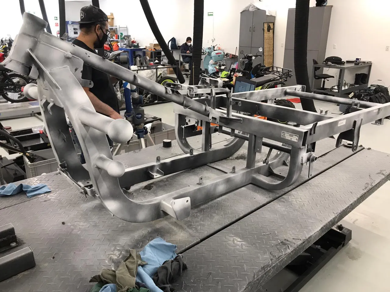
Tubular frame (primary system · highest criticality). The most complex system in the project: the frame is the structural backbone that transmits and distributes all dynamic loads of the motorcycle-rider assembly. The scan captured the complete 3D geometry of the tubular frame, the welded joints, the engine mounting points, the front and rear suspension mounts and the seat subframe. Parametric reconstruction in Autodesk Inventor used design-intent modeling — idealized geometry free of manufacturing distortion — with tube wall thickness and node positions adjusted to the NOM standard. FEA validation assessed static loads, fatigue cycles (500,000 cycles) and safety factors at the critical joints.
Engine and transmission systems (secondary system · high criticality). Engine scanning focused on the interfaces with the frame (mounting crankcases, vibration dampers and drive shaft position), which dictate the geometry of the frame mounts. The engine's internal cavities, lubrication channels and piston geometry were documented through as-built modeling to verify assembly clearances and mounting tolerances. The engine housing material (aluminum alloy) was characterized by X-ray fluorescence (XRF) analysis to specify the equivalent alloy available in the domestic market.
Front and rear suspension (tertiary system · medium-high criticality). The suspension components — front telescopic fork, rear swingarms and shock absorbers — were documented both geometrically and in terms of dynamic behavior. The scan captured the geometry of the guide elements and their working travel. FEA simulation assessed impact loads on the suspension system under Mexican road profiles, determining the safety factors required to meet NOM-068-SCFI criteria. The suspension mounts on the frame were the point where the three systems converged.
05Process
Design-intent reverse engineering methodology.
Each stage produces a verifiable technical deliverable. The FEA validation gate is mandatory before the CAD package is released to manufacturing.
Dimensional capture with the FARO Scan Arm — field metrology
The FARO Scan Arm combines a portable 7-axis measuring arm with an integrated laser line scanner in a single instrument, delivering high-precision contact data (±0.025 mm) on critical geometry along with surface point clouds for the frame's organic contours. The engine-to-frame mounting points, tubular weld nodes and suspension mounting holes were measured by contact. The frame's continuous surfaces, fairing mounts and fork guides were captured by laser scanning. Full capture of the frame, engine and suspension was completed in three working days, producing a point cloud of more than 12 million points at 0.5 mm resolution. FARO Scan Arm · ±0.025 mm · 12M+ points · 3 days of capture.
Design-intent parametric reconstruction in Autodesk Inventor
The point cloud was imported into Autodesk Inventor as a reconstruction reference. Design-intent modeling does not replicate the manufacturing deviations of the original Asian part — it rebuilds the design intent: idealized, symmetric geometry with clean, normalized dimensions free of weld distortion, surface wear or process variation. Each frame tube was rebuilt with its correct nominal dimensions, parameterized bend radii and wall thicknesses adjusted to the minimum required by NOM. Engine mounts and suspension anchor points were modeled with ±0.1 mm assembly tolerances to ensure interchangeability between domestic suppliers. Autodesk Inventor · Design-intent modeling · Assembly tolerances ±0.1 mm.
FEA simulation — critical loads, safety and fatigue
The Autodesk Inventor simulation module ran four types of analysis on the complete frame assembly: static analysis (distributed rider + motorcycle load under maximum acceleration and emergency braking), modal analysis (natural frequencies identified to avoid resonance with the engine frequency), fatigue analysis (500,000 cycles under a variable Mexican road load profile) and side impact analysis (NOM rollover test criterion). Material properties were set to the elastic and fatigue values of ASTM A500 Grade B structural steel available in the domestic market — ensuring the CAD package references locally manufacturable materials, not proprietary Asian alloys. Static FEA · Modal · 500K-cycle fatigue · NOM side impact · ASTM A500 Gr-B.
Regulatory adjustment — NOM compliance and redesign of non-conforming areas
Comparing the original Asian design with the requirements of the Mexican Official Standards identified three non-conforming areas: the minimum rear tire footprint width (NOM-068-SCFI), the safety factor at the frame-to-subframe joint under side impact load (below the required 1.5) and the position of the exhaust system mounts relative to the minimum heat clearance to the plastic fairing (NOM-044-SEMARNAT). All three areas were redesigned directly in the parametric CAD model, re-simulated and verified until full compliance was reached before the final package was generated. NOM compliance · 3 areas redesigned · Safety factor ≥1.5 · Re-simulation.
Complete CAD package and tender to domestic manufacturing
The final engineering package delivered to ITALIKA contains: parametric CAD models in native Inventor format + STEP for every component of the three systems, manufacturing drawings with GD&T dimensioning for tendering to domestic tube bending, structural welding and machining shops, material specifications with Mexican and imported alloy equivalents, an FEA simulation report with the results and safety factors of each analysis, and a bill of materials (BOM) referencing domestic raw material suppliers. ITALIKA has full ownership of the package for unrestricted use in manufacturing, future modifications and supplier management. CAD package · GD&T drawings · BOM · Domestic suppliers · Owned by ITALIKA.
06Finite element validation
No part is made without passing simulation.
FEA is not an extra step — it is the release gate for the CAD package. Without validation, there is no manufacturing authorization.
| Component / area | Analysis type | Load condition | Result | Status |
|---|---|---|---|---|
| Frame node — engine mount | Static + Fatigue | Combined tension/torsion load + 500,000 cycles | Safety factor 2.1 — fatigue above the limit at 10⁷ cycles | ✓ Approved |
| Frame-to-subframe joint (seat area) | Static + Impact | NOM side rollover load — 2.5× rider weight | Safety factor 1.8 (redesigned from the original 1.3) | ✓ Approved |
| Front suspension mounts | Dynamic + Modal | 3G pothole impact + natural frequency analysis | Frame natural frequency 24 Hz — outside the engine excitation range | ✓ Approved |
| Rear swingarms | Fatigue | Mexican road profile — asymmetric cyclic load | Calculated service life: 12 years / 80,000 km under standard use | ✓ Approved |
| Frame node — exhaust mount anchor (original design) | Thermal + Static | Operating temperature + engine vibration load | Safety factor 1.1 — below the required NOM minimum | ⚠ Redesigned |
07Regulatory framework
Designed to standard. Made in Mexico.
Regulatory compliance is not a final verification step — it is built into the CAD model as a design criterion.
- NOM-068-SCFI-2000 — Safety requirements for motorcycles and mopeds. Criteria for structural strength, minimum footprint dimensions and safety factors in the frame's critical load areas.
- NOM-044-SEMARNAT-2017 — Maximum permissible limits for hydrocarbon, CO and NOx emissions from motorcycles. Dictates the position and design of the exhaust system mounts integrated into the frame.
- NOM-009-SCT2-2008 — Specifications for vehicle lighting and signaling devices. Determines the anchor points on the frame and subframe for headlights, taillights and reflectors.
- NOM-086-SCFI-1994 — Technical characteristics of motorcycle tires and wheels. Constrains the rear swingarm geometry, the wheelbase and the width of the wheel mounting area.
08Process documentation
From physical component to parametric model.
09Technology stack
The tools that make localization possible.
- Dimensional capture — FARO Scan Arm. A portable 7-axis measuring arm with an integrated laser line scanner. It combines high-precision contact measurement (±0.025 mm) for critical geometry with surface scanning for continuous contours — all in a single instrument without switching tools. The Scan Arm's portability allows work directly on the component in the shop without removing it from the vehicle.
- CAD design and reconstruction — Autodesk Inventor. An integrated platform for parametric modeling, assembly management and simulation. The FARO point cloud is imported as a reference mesh body, and the design-intent parametric model is built on top of it. Native integration with the FEA simulation module eliminates exporting and importing between platforms, keeping full traceability between geometry, material and analysis results.
- Structural validation — FEA simulation in Autodesk Inventor. The finite element analysis module built into Inventor. It supports static, modal, thermal and fatigue analysis on the same CAD model with no format conversions. Material properties were set using data for ASTM A500 Gr-B structural steel available in Mexico, so that FEA results match exactly the material the domestic manufacturing supplier will use.
- Material characterization — XRF (X-ray fluorescence) analysis. Non-destructive elemental analysis by X-ray fluorescence of the original aluminum components (engine crankcase, cylinder head) to determine the chemical composition of the Asian alloy and find the closest equivalent available in the domestic market — without destroying the reference part.
- Technical documentation — GD&T drawings + PPAP package. The engineering package delivered to ITALIKA includes drawings with GD&T (Geometric Dimensioning & Tolerancing) per ASME Y14.5 for each component, ready for tendering to domestic suppliers. The documentation follows the automotive PPAP (Production Part Approval Process) framework to ease integration with ITALIKA's IATF 16949 supply chain.
- Local manufacturing — Domestic supplier network. The CAD package was designed for manufacturing processes available in Mexico: CNC bending of structural steel tube, MIG/TIG welding with AWS D1.1 certification, precision machining on CNC centers for anchor points, and surface treatment (shot blasting + epoxy paint). Choosing domestic suppliers over importing finished components drove the 40% reduction in total production cost.
10Value proposition
Why reverse engineering is the fastest route to localization.
- Production cost savings (–40%). The total cost of importing a motorcycle from Asia includes ocean freight, tariffs, customs inspection, port storage, inland freight and the cost of inventory in transit over a 6–8 week logistics cycle. Local manufacturing eliminates the entire logistics component and reduces exposure to exchange rates. The 40% savings is not a one-off estimate — it is the structural impact of replacing the import chain with the domestic supply chain.
- Accelerated development cycle (8 wks). The conventional development cycle for a localized component — from requesting drawings from the original manufacturer to approving the replacement supplier — can stretch to 12–18 months if license negotiations or redesign without reference data are involved. Reverse engineering with the FARO Scan Arm and Autodesk Inventor compresses that cycle to 8 weeks: from physical component to an FEA-validated CAD package ready for tendering, with no dependence on the original manufacturer.
- Local intellectual property (100%). The resulting CAD package — parametric models, GD&T drawings, FEA reports and BOM — is fully owned by ITALIKA from day one of delivery. No usage licenses, no modification restrictions, no dependence on an engineering provider for future changes. The design know-how stays with the domestic manufacturer, enabling iterations, product variants and optimizations independently.
Technical sheet
Technical specifications
- Capture and metrology — Instrument: FARO Scan Arm — portable 7-axis arm with integrated laser scanner
- Capture and metrology — Volumetric accuracy: ±0.025 mm (25 microns per meter)
- Capture and metrology — Point cloud resolution: 0.5 mm — 12 million points total
- CAD modeling — Software: Autodesk Inventor — parametric modeling with a complete feature tree
- CAD modeling — Assembly tolerances: ±0.1 mm at interfaces between systems
- CAD modeling — Delivery formats: .ipt / .iam (native Inventor) + .STEP + .DWG / .PDF drawings with GD&T
- FEA simulation — Static analysis: combined rider load + braking and acceleration dynamics
- FEA simulation — Modal analysis: natural frequency identification — 0–100 Hz range
- FEA simulation — Fatigue analysis: 500,000 cycles — Mexican urban road profile
- FEA simulation — Base FEA material: ASTM A500 Gr-B steel — available in the domestic market
- Results and deliverables — Total project time: 8 weeks from first scan to released package
Related services
Capabilities that complement this case
Combining capture, engineering, simulation, manufacturing and metrology makes it possible to control the entire workflow.
Reverse engineering
Reconstruction of geometry and design logic from physical components to produce CAD models ready for redesign or manufacturing.
3D scanning
Dimensional capture of components and surfaces with digitization tools, providing a verifiable geometric reference.
FEA / CFD simulation
Numerical validation of geometry and components before manufacturing, including structural analysis and assessment of critical load conditions.
Do you have a similar technical challenge?
Share the files you have, the expected result and the project timeline. We will review the case and propose the right workflow.